
NOTE: This topic is for reference only. Refer to the I/O Frame 8s User Manual for installation instructions.
The I/O Frame 8s, running a customized Linux operating system, provides one of the main input and output connection devices for the Q-SYS system. The Core connects to the I/O Frame 8s via the Q-SYS network, limiting the number of I/O Frames only to the size of your Core, and network bandwidth. An I/O Frame 8s can contain up to eight of the available Audio I/O cards.
This topic covers the hardware aspect of the I/O Frame. For configuration details in Q-SYS Designer, refer to the I/O Frame configuration topic.
NOTE: When an I/O Frame is shipped, the I/O cards that are installed in the I/O Frame at shipping, are noted on the shipping label.
Type 2 hardware provides new cables and connectors between the I/O cards and main boards in Cores and I/O Frames. Due to this change, the Type 2 hardware is not physically compatible with the older hardware. You can still integrate the new I/O Frames and Cores in the same system with older hardware, but the I/O cards are not interchangeable. Type 2 hardware can be identified by a yellow label on the back of the Core and I/O Frame, and the bottom of the I/O cards.
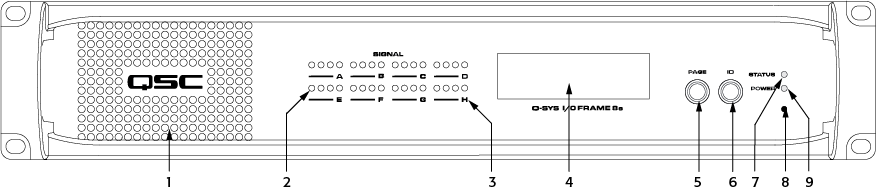
Five pages of information
Scrolls through the LCD readout pages
VIDEO TUTORIAL: Video presentation available online for Identify Device Button.
VIDEO TUTORIAL: For a comparison of the Front and Back Panel with a Core, watch the video presentation of the Core and I/O Frame.
Insert a paperclip or similar device into the reset hole and hold for 10 seconds. A timer displays on the LCD. This resets all network settings to their factory defaults: IP Addresses, hostname, etc.
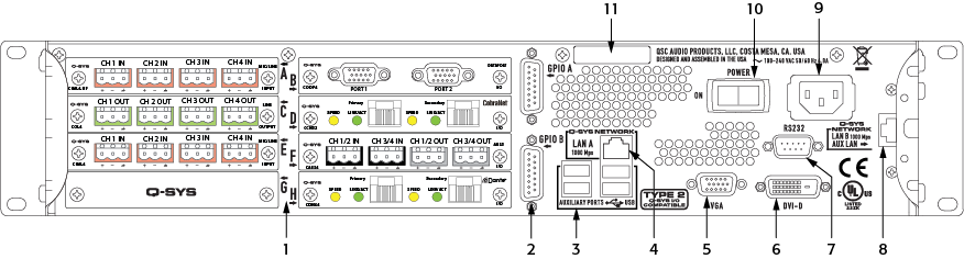
The I/O Frame allows for combinations of eight, of the following I/O cards.
NOTE: The types of cards shown in the example above are for illustration purposes only.
|
System Hardware |
I/O Frame |
|---|---|
|
Description |
System audio input and output device – eight I/O card slots. |
|
Front Panel Controls |
|
|
Front Panel Indicators |
|
|
Rear Panel Controls |
|
|
Rear Panel Connectors |
|
|
Capacity |
|
|
Local Audio Channels |
128 x 128 |
|
Network Audio Channels In |
128 |
|
Network Audio Channels Out |
128 |
|
Audio I/O Capacity |
Eight I/O Card Slots, Supporting: up to 32 analog I/O channels or up to 128 x 128 local digital I/O channels; Requires purchase of Q-SYS Type 2 audio I/O cards: CB, CIML4, CIML4-HP, COL4, CODP4, CAES4, CCN32, CDN64, CAN32. |
|
Line Voltage Requirements |
100 VAC - 240 VAC, 47 - 63 Hz |
| Current Draw |
Max 4.8 A @ 100 VAC |
|
Typical 1.9 A @ 100 VAC |
|
| Thermal | 650 BTU/h (typical) |
|
Dimensions (HWD) |
3.5" × 149" × 16.13" (88.9 mm × 482.6 mm × 425.7 mm) / 2RU |
|
Accessories Included |
|
© 2009 - 2016 QSC, LLC. All rights reserved. QSC and the QSC logo are trademarks of QSC, LLC in the U.S. Patent and Trademark office and other countries. All other trademarks are the property of their respective owners.
http://patents.qsc.com.
![]()
 Related Topics